|
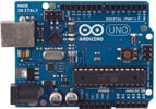
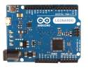
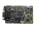
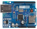
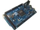
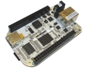
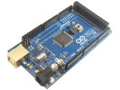
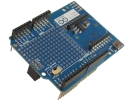
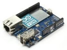
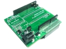
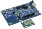
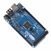
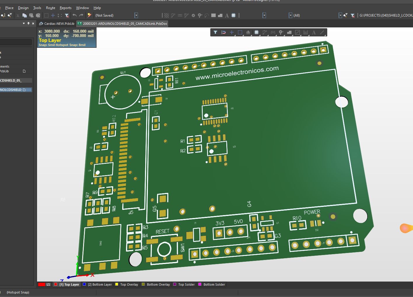
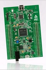
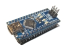
The board contains everything needed to support the microcontroller; simply connect it to a computer with a micro-USB cable or power it with a AC-to-DC adapter or battery to get started. The Due is compatible with all Arduino shields that work at 3.3V and are compliant with the 1.0 Arduino pinout.
The Due follows the 1.0 pinout:
- TWI: SDA and SCL pins that are near to the AREF pin.
- The IOREF pin which allows an attached shield with the proper configuration to adapt to the voltage provided by the board. This enables shield compatibility with a 3.3V board like the Due and AVR-based boards which operate at 5V.
- An unconnected pin, reserved for future use.
The Due has a dedicated forum for discussing the board.
ARM Core benefits
The Due has a 32-bit ARM core that can outperform typical 8-bit microcontroller boards. The most significant differences are:
- A 32-bit core, that allows operations on 4 bytes wide data within a single CPU clock. (for more information look int type page).
- CPU Clock at 84Mhz.
- 96 KBytes of SRAM.
- 512 KBytes of Flash memory for code.
- a DMA controller, that can relieve the CPU from doing memory intensive tasks.
Summary
| - Microcontroller |
|
AT91SAM3X8E |
| - Operating Voltage |
|
3.3V |
| - Input Voltage (recommended) |
|
7-12V |
| - Input Voltage (limits) |
|
6-20V |
| - Digital I/O Pins |
|
54 (of which 12 provide PWM output) |
| - Analog Input Pins |
|
12 |
| - Analog Outputs Pins |
|
2 (DAC) |
| - Total DC Output Current on all |
|
130 mA |
| - DC Current for 3.3V Pin |
|
800 mA |
| - DC Current for 5V Pin |
|
800 mA |
| - Flash Memory |
|
512 KB all available for the user applications |
| - SRAM |
|
96 KB (two banks: 64KB and 32KB) |
| - Clock Speed |
|
84 MHz |
- Power
The Arduino Due can be powered via the USB connector or with an external power supply. The power source is selected automatically.
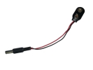
External (non-USB) power can come either from an AC-to-DC adapter (wall-wart) or battery. The adapter can be connected by plugging a 2.1mm center-positive plug into the board's power jack. Leads from a battery can be inserted in the Gnd and Vin pin headers of the POWER connector.
The board can operate on an external supply of 6 to 20 volts. If supplied with less than 7V, however, the 5V pin may supply less than five volts and the board may be unstable. If using more than 12V, the voltage regulator may overheat and damage the board. The recommended range is 7 to 12 volts.
The power pins are as follows:
- VIN. The input voltage to the Arduino board when it's using an external power source (as opposed to 5 volts from the USB connection or other regulated power source). You can supply voltage through this pin, or if supplying voltage via the power jack, access it through this pin.
- 5V. This pin outputs a regulated 5V from the regulator on the board. The board can be supplied with power either from the DC power jack (7 - 12V), the USB connector (5V), or the VIN pin of the board (7-12V). Supplying voltage via the 5V or 3.3V pins bypasses the regulator, and can damage your board. We don't advise it.
- 3.3V. A 3.3 volt supply generated by the on-board regulator. Maximum current draw is 800 mA. This regulator also provides the power supply to the SAM3X microcontroller.
- GND. Ground pins.
- IOREF. This pin on the Arduino board provides the voltage reference with which the microcontroller operates. A properly configured shield can read the IOREF pin voltage and select the appropriate power source or enable voltage translators on the outputs for working with the 5V or 3.3V.
Memory
The SAM3X has 512 KB (2 blocks of 256 KB) of flash memory for storing code. The bootloader is preburned in factory from Atmel and is stored in a dedicated ROM memory. The available SRAM is 96 KB in two contiguous bank of 64 KB and 32 KB. All the available memory (Flash, RAM and ROM) can be accessed directly as a flat addressing space.
It is possible to erase the Flash memory of the SAM3X with the onboard erase button. This will remove the currently loaded sketch from the MCU. To erase, press and hold the Erase button for a few seconds while the board is powered.
Input and Output
- Digital I/O: pins from 0 to 53
Each of the 54 digital pins on the Due can be used as an input or output, using pinMode(), digitalWrite(), and digitalRead() functions. They operate at 3.3 volts. Each pin can provide (source) a current of 3 mA or 15 mA, depending on the pin, or receive (sink) a current of 6 mA or 9 mA, depending on the pin. They also have an internal pull-up resistor (disconnected by default) of 100 KOhm. In addition, some pins have specialized functions:
- Serial: 0 (RX) and 1 (TX)
- Serial 1: 19 (RX) and 18 (TX)
- Serial 2: 17 (RX) and 16 (TX)
- Serial 3: 15 (RX) and 14 (TX)
Used to receive (RX) and transmit (TX) TTL serial data (with 3.3 V level). Pins 0 and 1 are connected to the corresponding pins of the ATmega16U2 USB-to-TTL Serial chip.
- PWM: Pins 2 to 13
Provide 8-bit PWM output with the analogWrite() function. the resolution of the PWM can be changed with the analogWriteResolution() function.
- SPI: SPI header (ICSP header on other Arduino boards)
These pins support SPI communication using the SPI library. The SPI pins are broken out on the central 6-pin header, which is physically compatible with the Uno, Leonardo and Mega2560. The SPI header can be used only to communicate with other SPI devices, not for programming the SAM3X with the In-Circuit-Serial-Programming technique. The SPI of the Due has also advanced features that can be used with the Extended SPI methods for Due.
- CAN: CANRX and CANTX
These pins support the CAN communication protocol but are not not yet supported by Arduino APIs.
- "L" LED: 13
There is a built-in LED connected to digital pin 13. When the pin is HIGH, the LED is on, when the pin is LOW, it's off. It is also possible to dim the LED because the digital pin 13 is also a PWM outuput.
- TWI 1: 20 (SDA) and 21 (SCL)
- TWI 2: SDA1 and SCL1.
Support TWI communication using the Wire library.
- Analog Inputs: pins from A0 to A11
The Due has 12 analog inputs, each of which can provide 12 bits of resolution (i.e. 4096 different values). By default, the resolution of the readings is set at 10 bits, for compatibility with other Arduino boards. It is possible to change the resolution of the ADC with analogReadResolution(). The Due's analog inputs pins measure from ground to a maximum value of 3.3V. Applying more then 3.3V on the Due's pins will damage the SAM3X chip. The analogReference() function is ignored on the Due.
The AREF pin is connected to the SAM3X analog reference pin through a resistor bridge. To use the AREF pin, resistor BR1 must be desoldered from the PCB.
- DAC1 and DAC2
These pins provides true analog outputs with 12-bits resolution (4096 levels) with the analogWrite() function. These pins can be used to create an audio output using the Audio library.
Other pins on the board:
- AREF
Reference voltage for the analog inputs. Used with analogReference().
- Reset
Bring this line LOW to reset the microcontroller. Typically used to add a reset button to shields which block the one on the board.
|
|
|


 Facebook
 Twitter
 Linkedin
 Youtube